Parametric Part Modeling
Editable models with dimensions and design relationships: shafts, bushings, plates, brackets, adapters, and custom components.
Prefer English? View in English
Prefere português? Ver em Português
¿Prefieres español? Ver en español
Vous préférez le français ? Voir en français
Бажаєте українською? Перейти на українську
Bevorzugen Sie Deutsch? Auf Deutsch ansehen
Wolisz język polski? Przejdź do polskiej wersji
Prefere a versão para o Brasil? Acessar Brasil
Services / CAD Modeling
CAD models of parts, assemblies and machines from sketches, drawings or files. Develop new designs or improve existing equipment to suit your requirements.
Your project
Send the dimensions, references, and result you need. We agree on the components, checks, and final files before work begins. You review the design and request the revisions included in your quote.
Specialist strength calculations, safety validation, physical testing, and certification are assessed separately when your application requires them.
Editable models with dimensions and design relationships: shafts, bushings, plates, brackets, adapters, and custom components.
Multi-part constructions, mounting connections, fits, component positions, and assembly order.
Hinged, rotating, sliding, and adjustable mechanisms, with movement and geometric limits defined for the agreed design.
Individual parts, auxiliary mechanisms, assemblies, or the agreed CAD portion of a larger industrial equipment project.
Roller assemblies, adjustable guides, belt tensioners, drive mounts, handling mechanisms, and packaging or dosing equipment components.
Profile frames, supports, mounting structures, and welded assemblies, with their geometry and connections developed around your requirements.
Bent parts, panels, brackets, covers, and flat patterns based on the agreed material, thickness, and fabrication parameters.
Component spaces, mounting points, openings, covers, and access for assembly and maintenance.
Jigs, clamps, holders, positioning devices, and auxiliary components for holding, machining, or assembling parts.
Develop an agreed idea into a technical construction: component layout, separate parts, connections, and a digital model for prototyping.
Rebuild CAD from measurements, drawings, scans, and existing parts, with critical dimensions clarified before modeling.
Change geometry, overall dimensions, components, mounting points, or layouts to meet new requirements. Imported STEP geometry may need reconstruction to restore editable features.
Develop the construction around the chosen process, fastener access, part count, connections, and assembly sequence.
Geometric checks of how components fit, move, and occupy space under the agreed conditions.
Part and assembly drawings, sections, dimensions, detail views, component identification, and parts lists.
Your task
Turn my dimensioned drawing into editable CAD for a part or assembly.
Adapt a machine bracket, frame, or enclosure to new mounting points and available space.
Maintain assembly models, related drawings, and revision records as our equipment evolves.
Design sheet-metal panels and flat patterns around my fabricator’s requirements.
Develop a drilling jig or assembly fixture to locate and hold my parts.
Lay out an adjustable guide, roller module, or sliding mechanism within the available space.
Develop a conveyor station layout with guides, stops, and connections to adjacent equipment.
Integrate specified motors, gearboxes, bearings, and other catalog components into an assembly.
Build a parametric product family so agreed sizes can change without redrawing each variant.
Mounting faces, hole patterns, mating parts, movement and available space establish the model’s constraints. We distinguish measured dimensions from assumptions and identify the interfaces that must remain unchanged. This gives revisions a clear basis and helps prevent a locally correct part from conflicting with the surrounding assembly.
A useful handover needs the agreed software version, referenced components and consistent drawing revisions. Native parametric files preserve a different level of editability from a STEP export. We define the assembly structure, source files, exchange formats and any parts list in the scope so your team can continue working with the result.
We check mounting faces, hole patterns, clearances and access for assembly before releasing the CAD files. For moving assemblies, we review the agreed positions and look for interference in the digital model. We verify the file revision and linked components at handover so the next change starts from a consistent assembly.
Process
Confirm what the part must do, its size, connections, and how it will be made.
Build the CAD model and review how the parts fit and assemble.
Make the included changes and deliver your models and drawings.
Your quote confirms which files are included.
We check dimensions, mating components, clearances, movement and assembly access. We correct conflicts and coordinate the parts and drawings before delivery, so you receive a consistent design prepared for the next manufacturing and physical testing stage.
Yes. We can develop the agreed mechanical design, from the equipment layout to parts, assemblies, drive integration and drawings. For a retrofit, we work around the interfaces that must remain. Operating requirements, specialist checks and the manufacturing scope are defined for the project.
Send the existing CAD or drawing and the change you need. We review mounting points, mating parts and available space, then agree the component redesign and any assembly drawings required.
Yes. Send the sketch or drawing, known dimensions, and what the part needs to do. We will clarify missing details before quoting.
Yes. We inspect your STEP file, make the required changes and rebuild features where needed. We check the revised geometry and its connections to the surrounding parts before delivery.
Yes, when included in your quote. Drawings can show views, sections, dimensions, mounting details, notes, and component identification. A BOM is the parts list for an assembly.
Request editable source files in your preferred CAD application and version before we quote. Neutral exchange files do not preserve all native features or modeling history.
Tell us which dimensions or components are likely to change. We can plan parameters, part relationships and a consistent assembly structure around those changes. The quote identifies the editable source and any size variants included; a STEP export alone does not retain the original feature history.
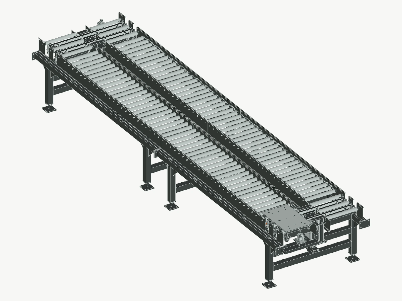
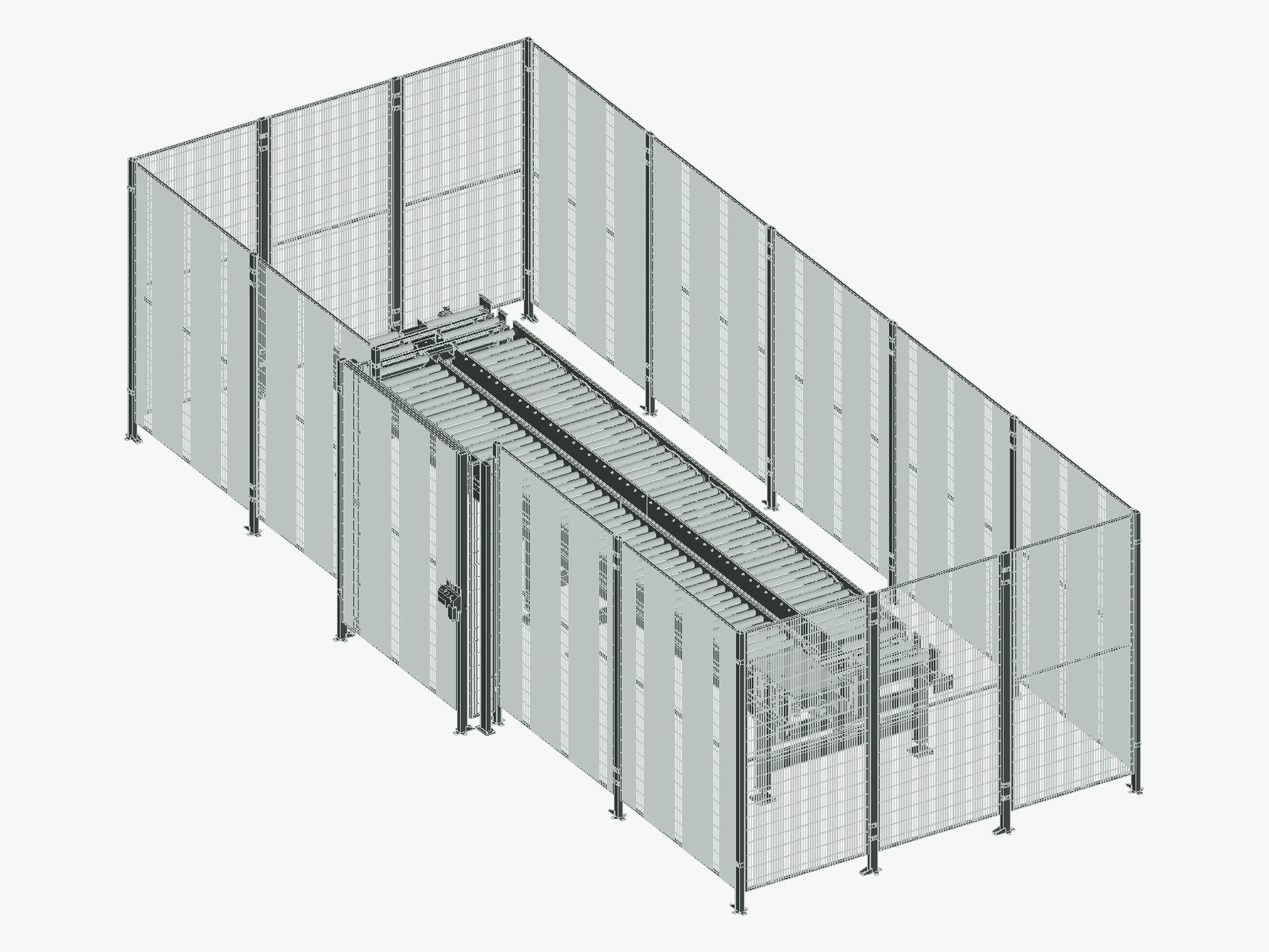
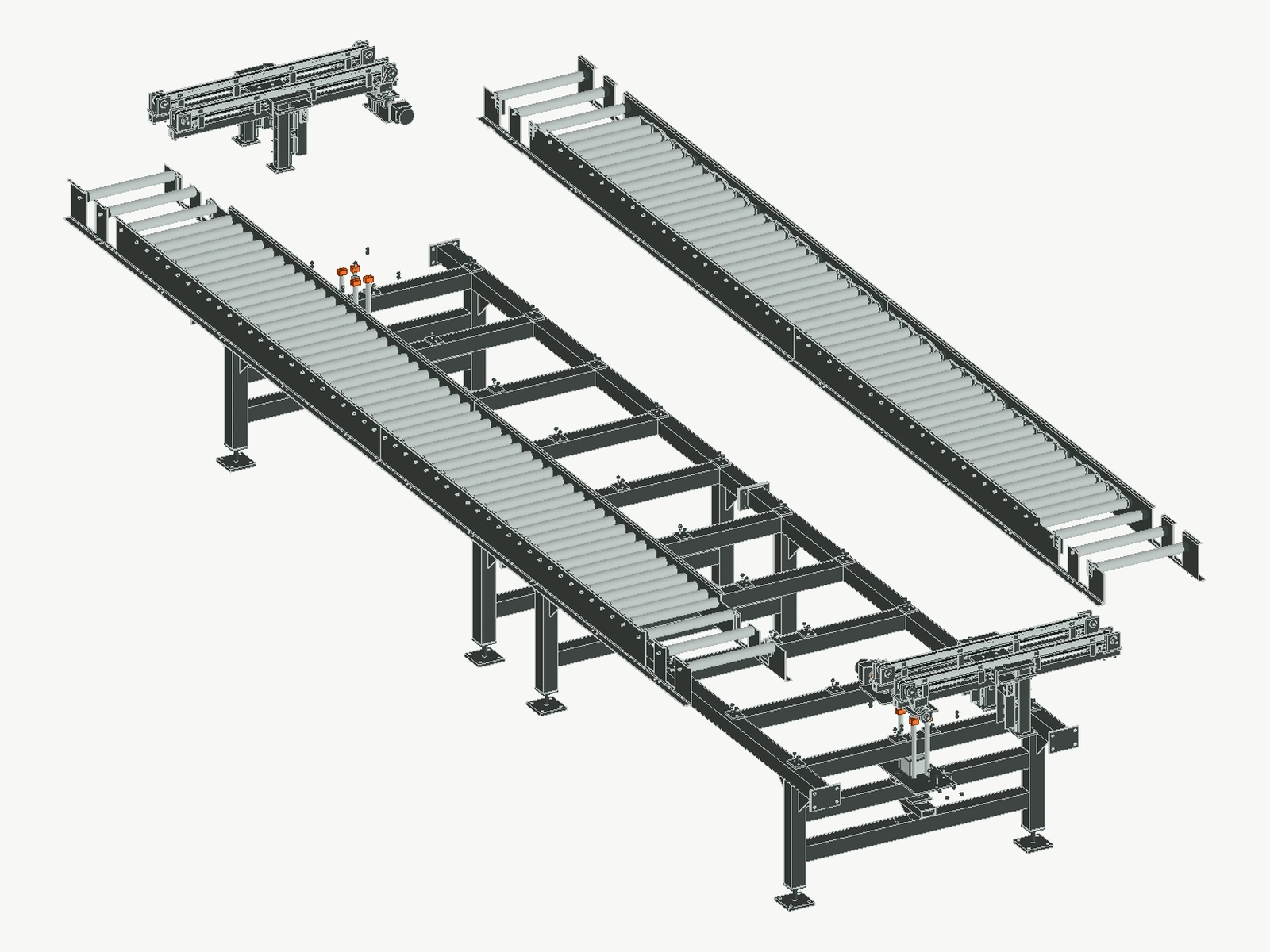
Mechanical CAD study of a 6 m twin-lane conveyor for 600 × 400 mm pallets, using a 20 kg gross pallet basis. The selected envelope is 6,184 × 1,440 × 930 mm. Ten holding zones serve up to eight pallets. Two 25 mm lift-and-transfer units connect the powered roller lanes, with damped stops, separate load guides and a coaxial brake connection.
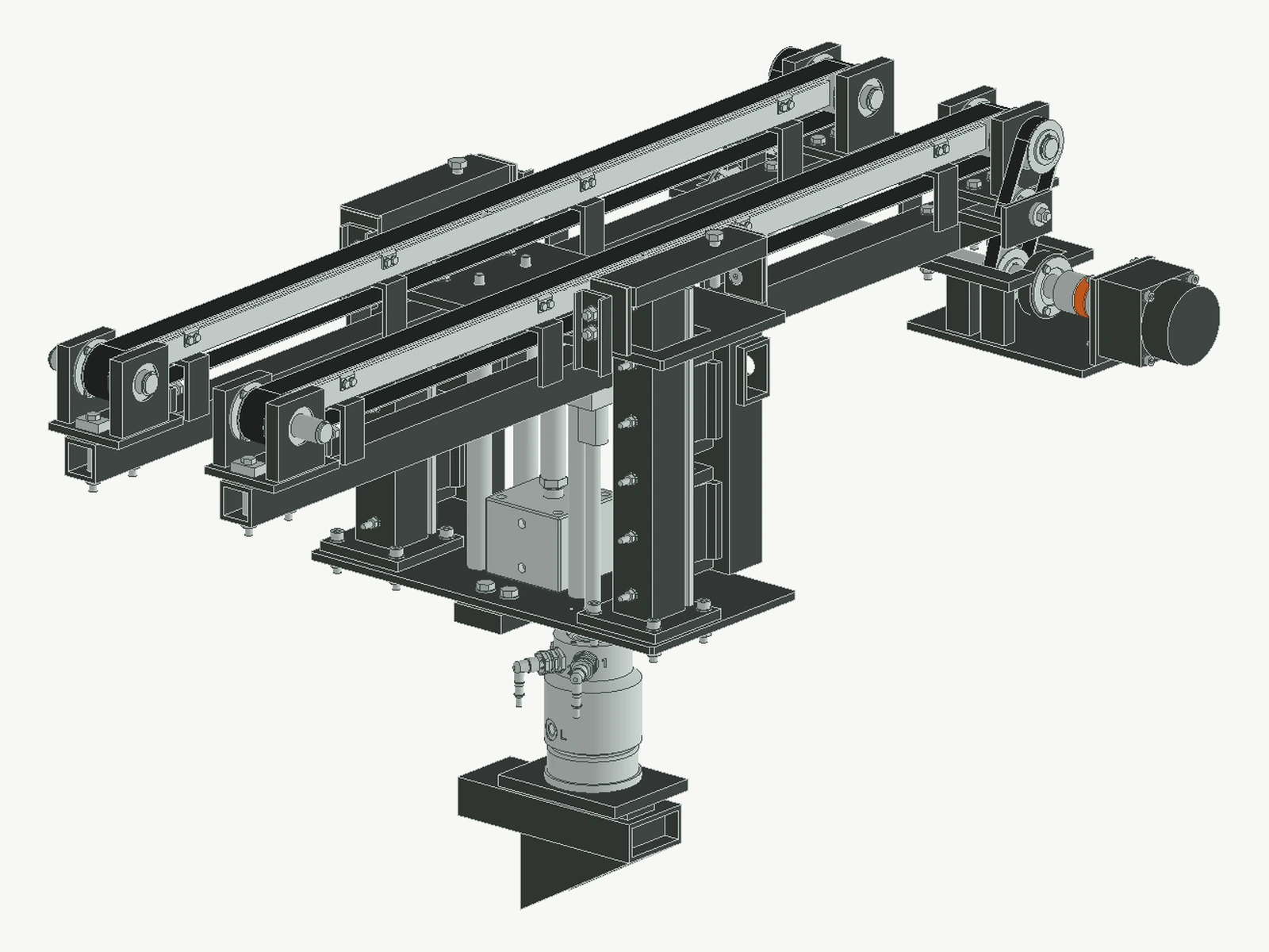
A 180 mm wide belt module with 40 mm drums, screw-adjusted bearing carriers and a separately supported drive shaft. Designed for rigid cartons from 140 mm long, with access for belt and coupling servicing.


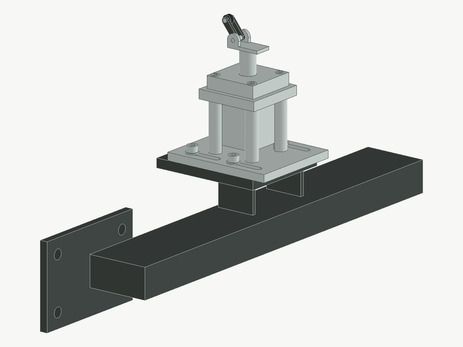
A 100 mm stroke feed module with independent shaft guidance, a floating cylinder connection and a replaceable contact pad. The design addresses cylinder side loading and provides access to service components.
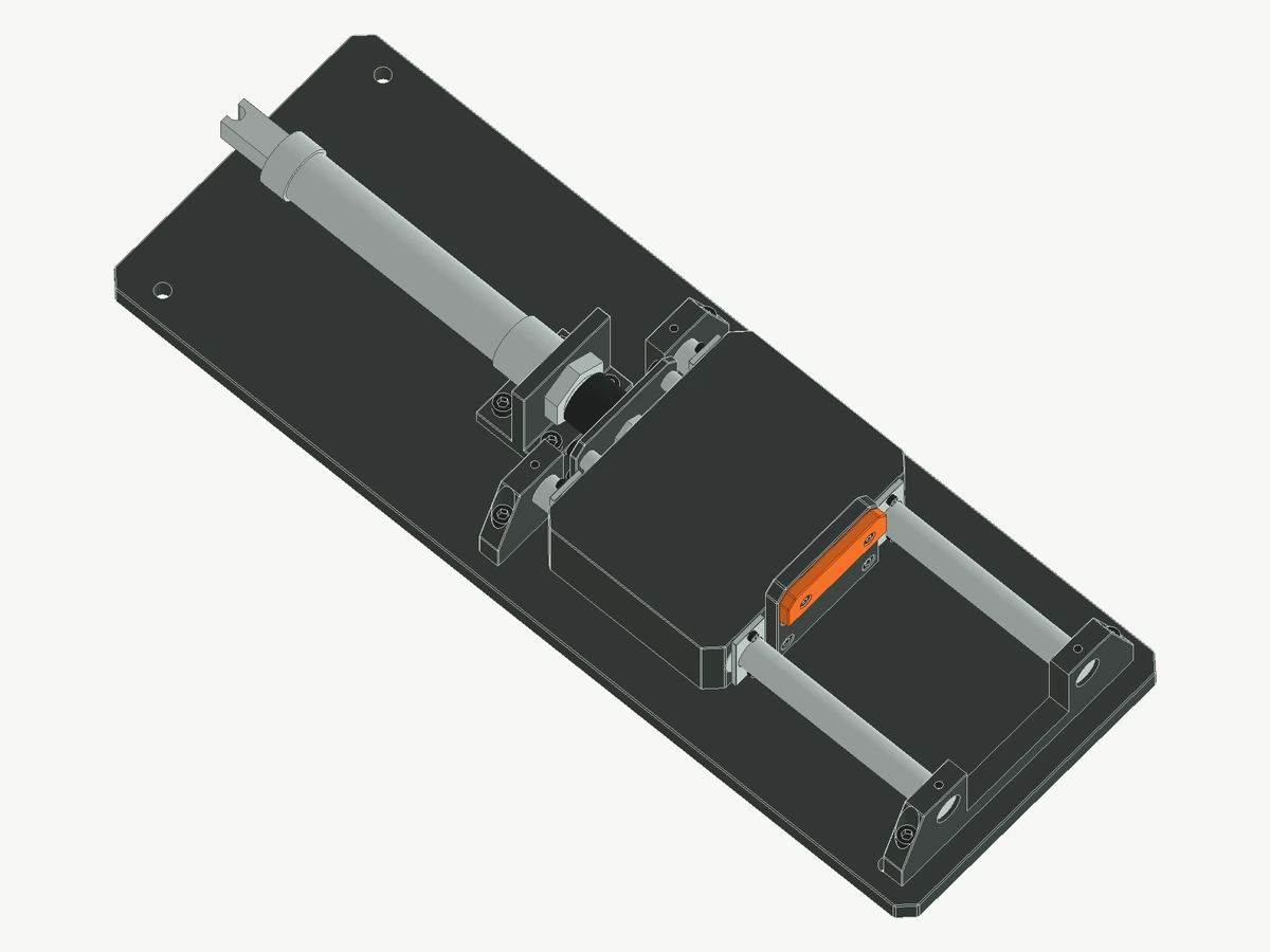
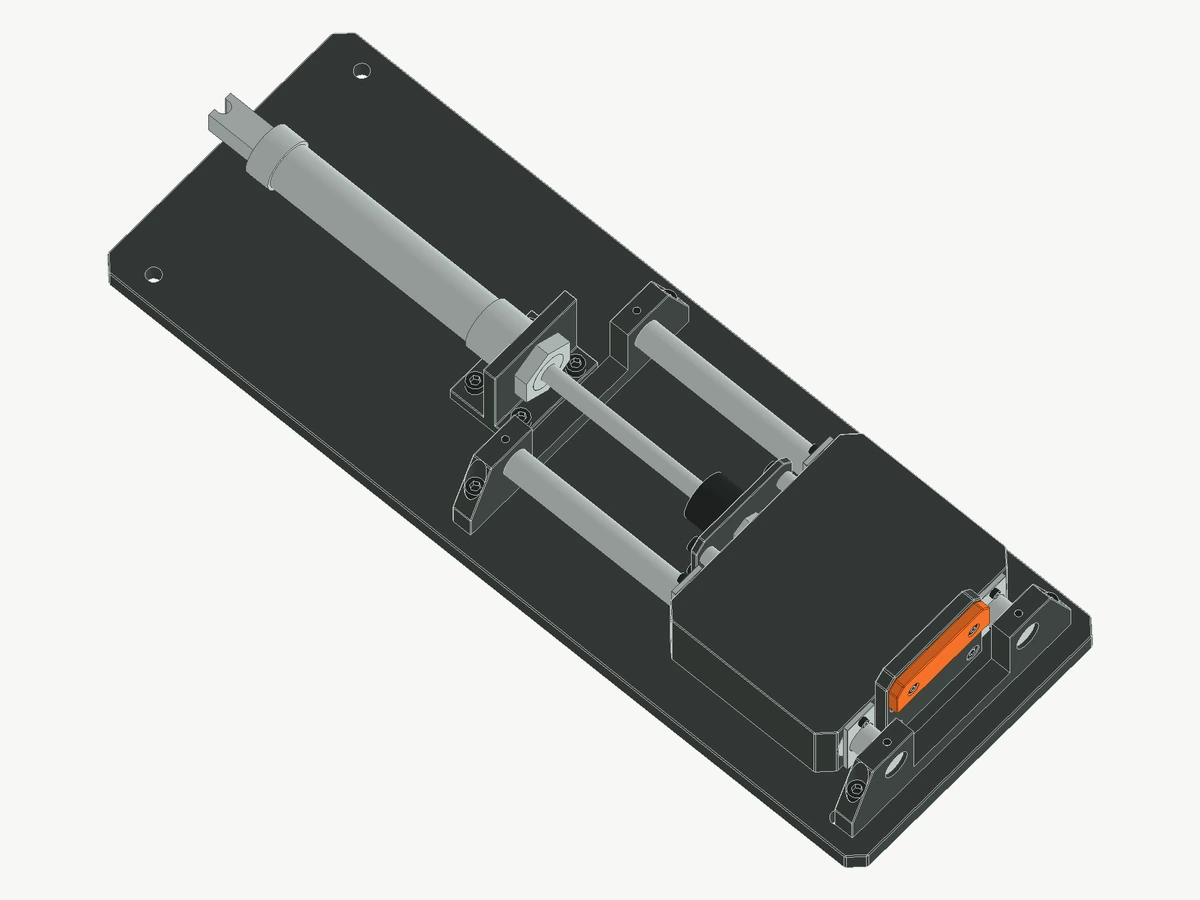
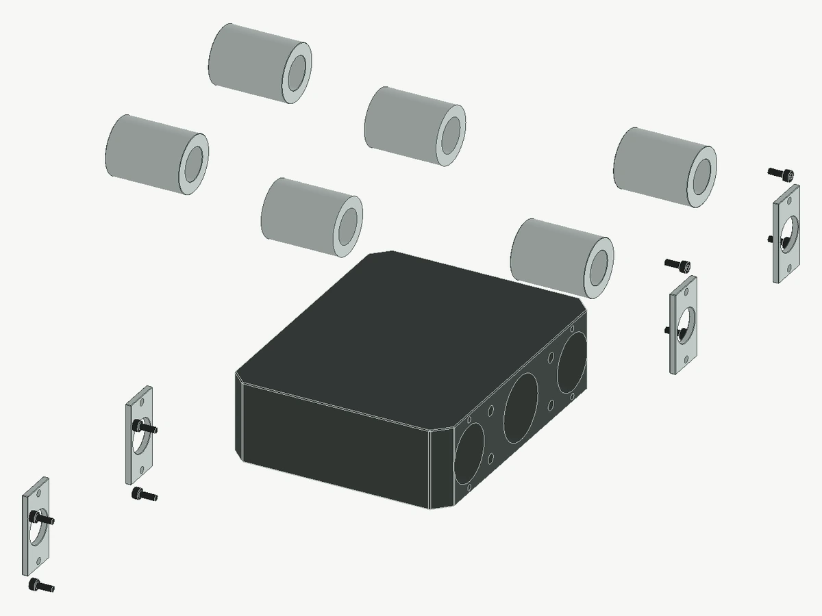
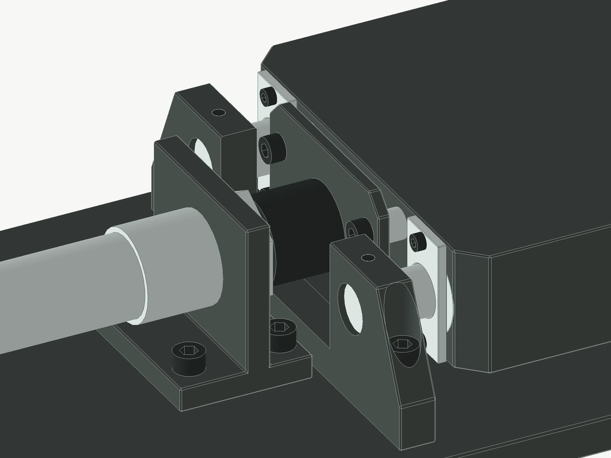
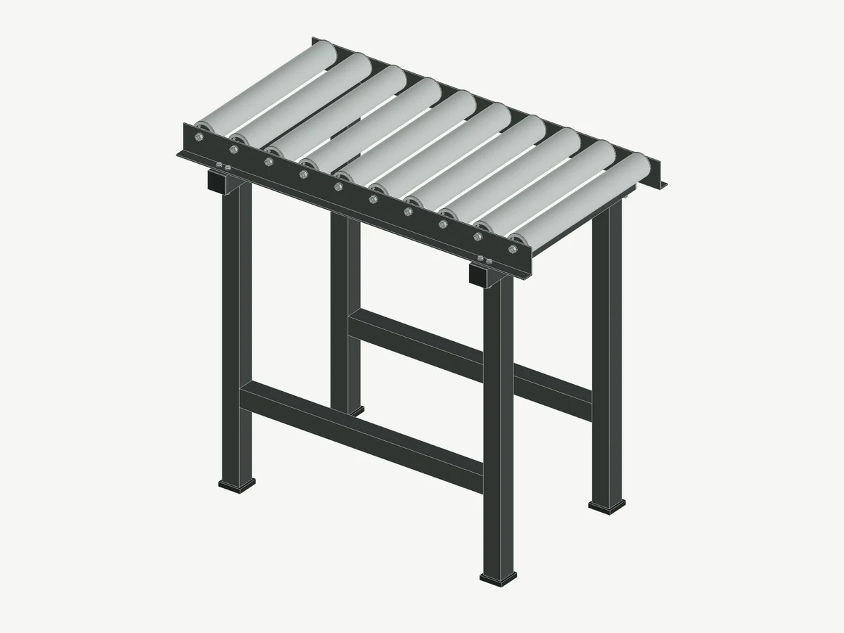
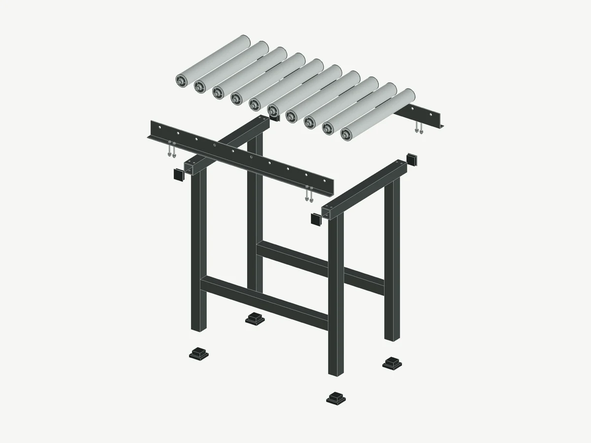
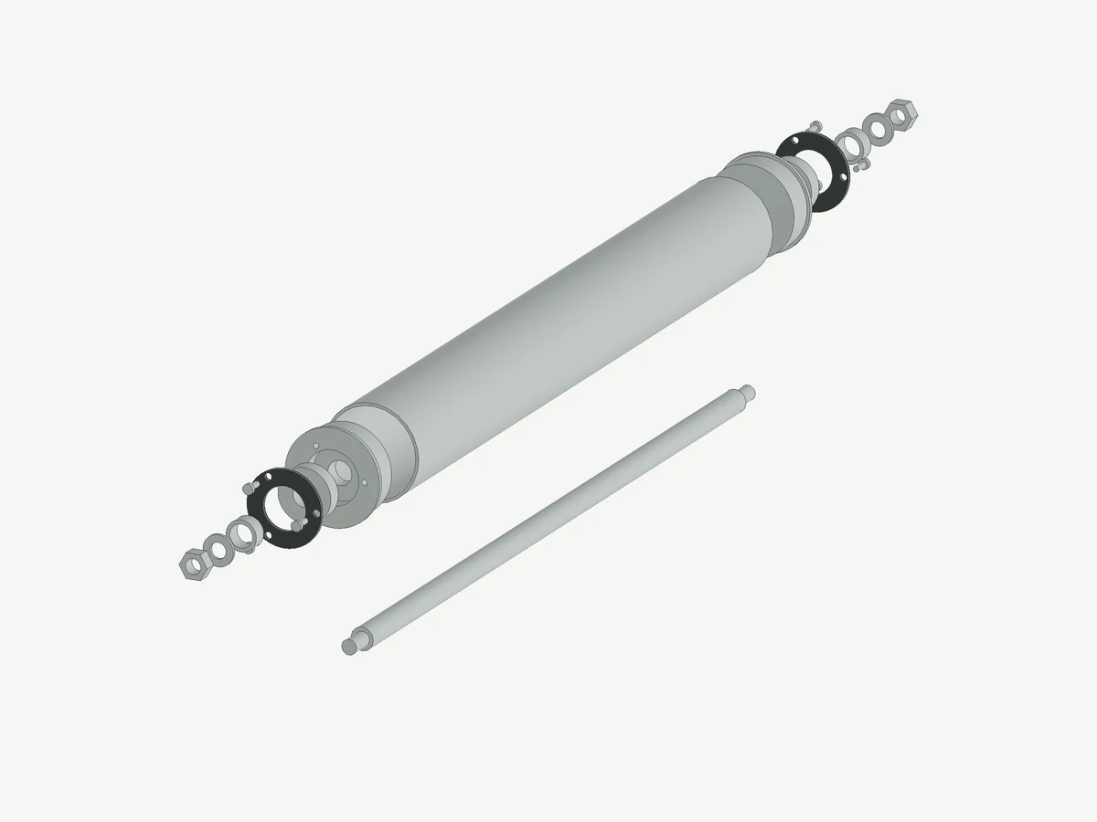
A compact conveyor for transferring boxes between packing tasks. The design brings together the support frame, rollers, shafts, and their assembly connections.
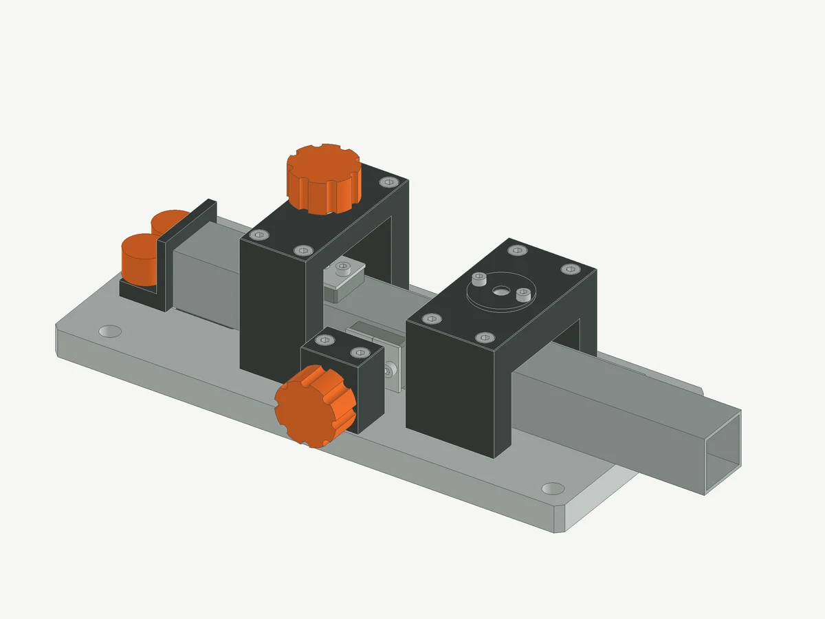
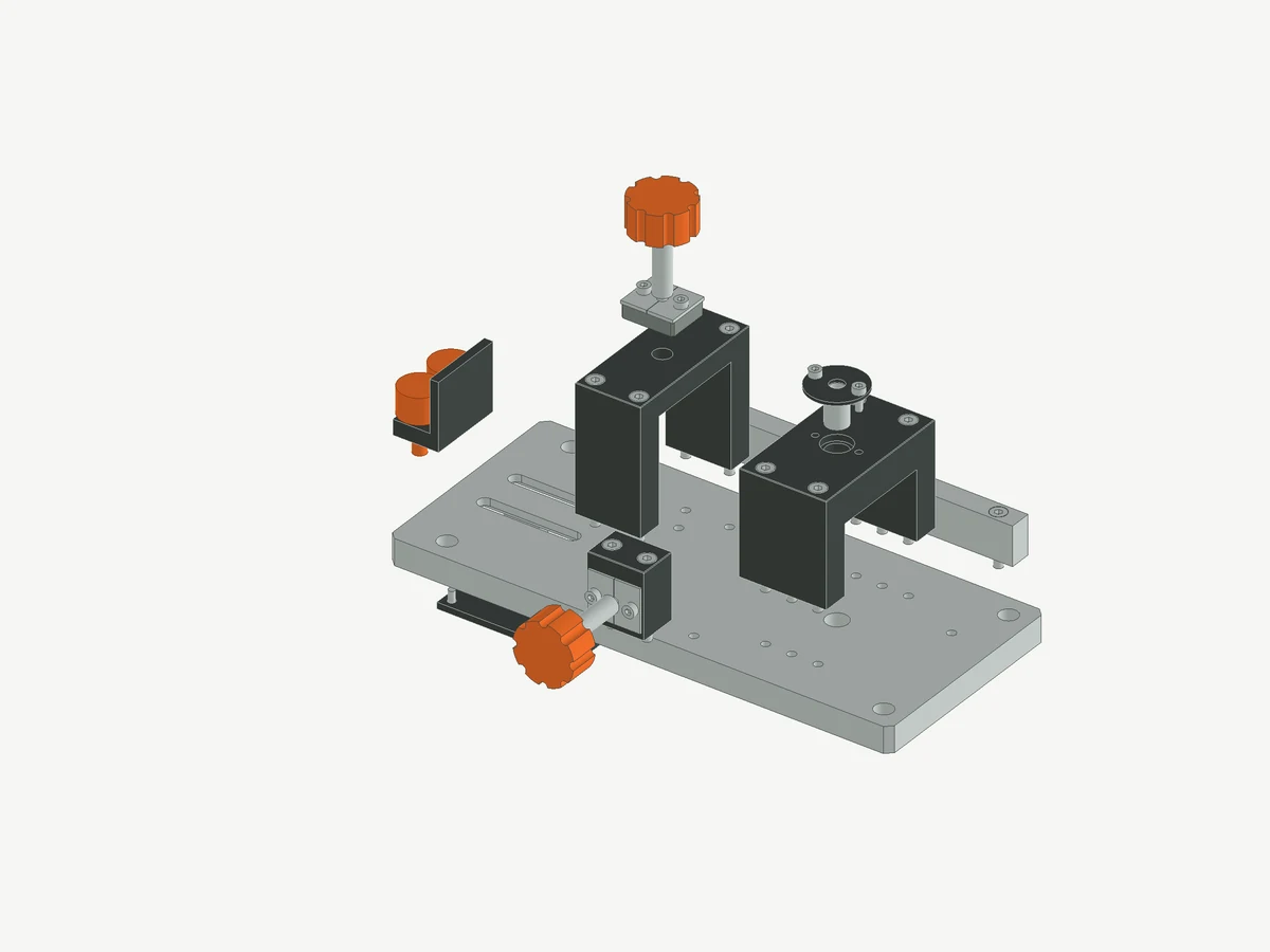
A drilling fixture for 25 × 25 mm square tubing. An adjustable end stop positions the tube, two screw clamps hold it, and a replaceable Ø6 mm bushing guides the drill.

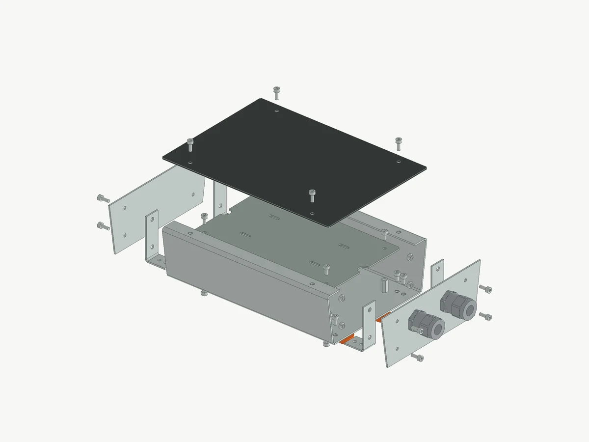
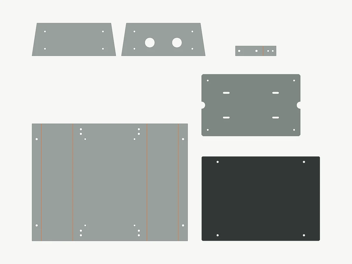
A controller housing designed around 1.5 mm aluminum sheet, a removable 160 × 100 mm mounting plate, and two M16 cable glands. The views show how the panels fit together and how the sheet parts unfold.
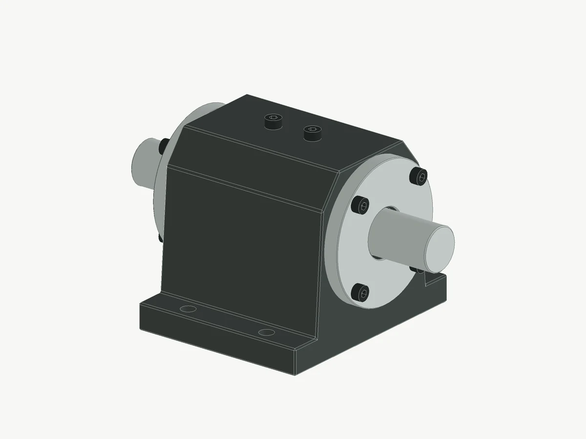
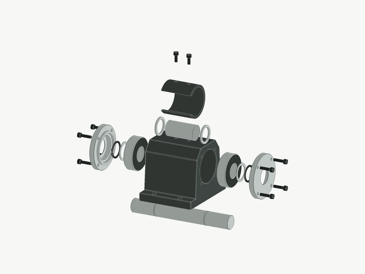
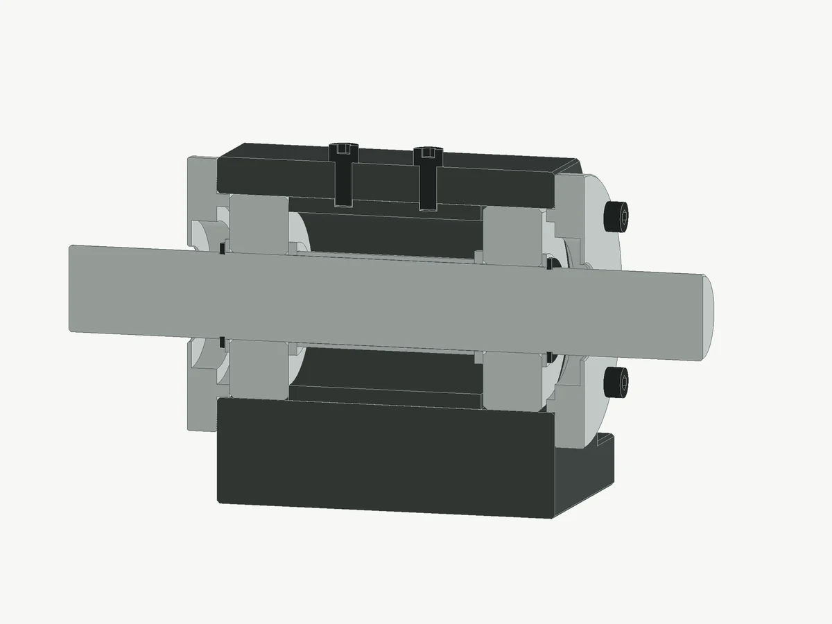
A compact housing for a Ø20 mm shaft supported by two 20 × 47 × 14 mm bearings. Removable end covers provide access, while retaining rings locate the shaft. The section view shows the internal arrangement.
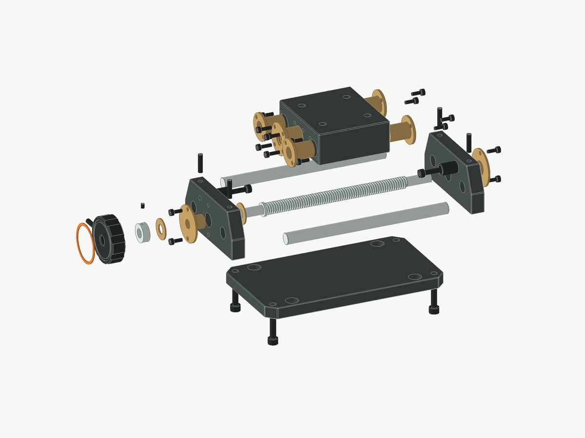
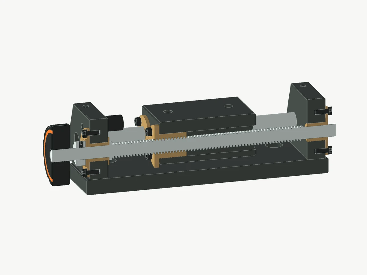
A manual positioning platform with 40 mm of travel on a 160 × 90 mm base. The handwheel turns a screw drive, while two guide shafts support the moving carriage. Replaceable bushings and end stops complete the assembly.

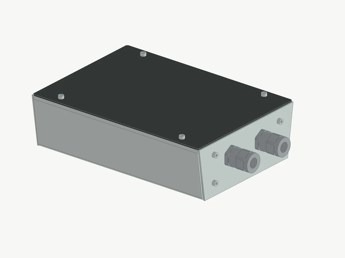
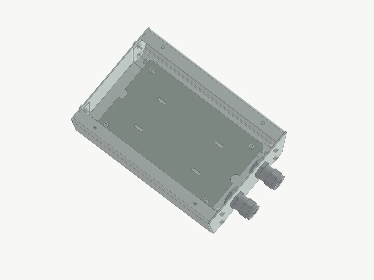
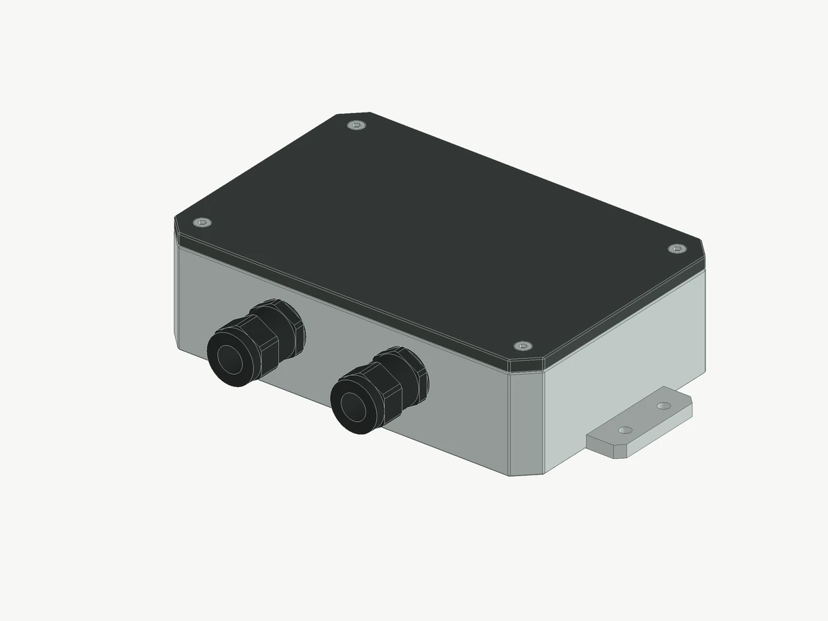
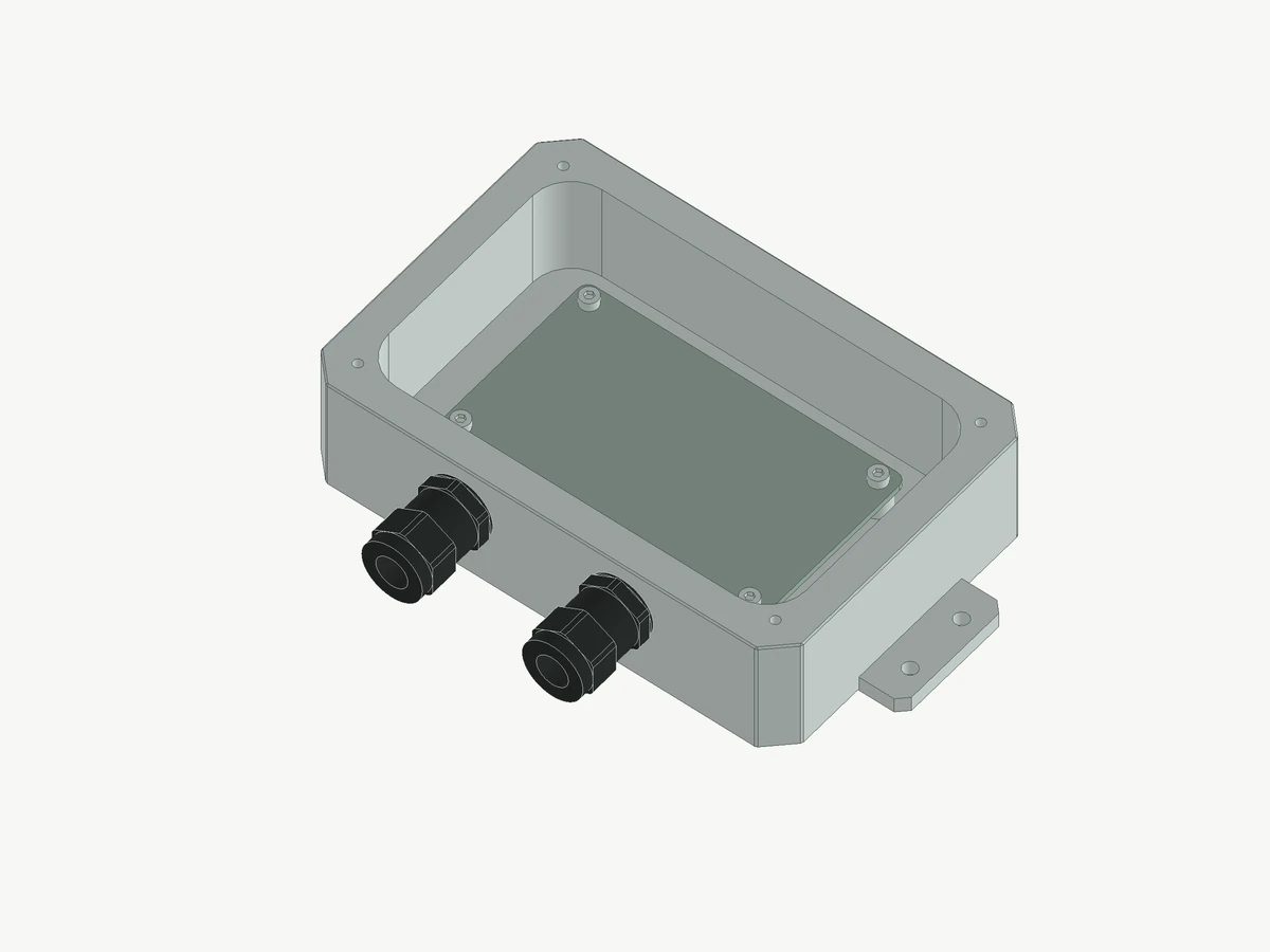
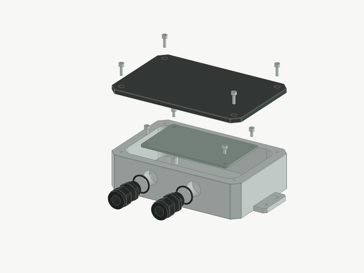
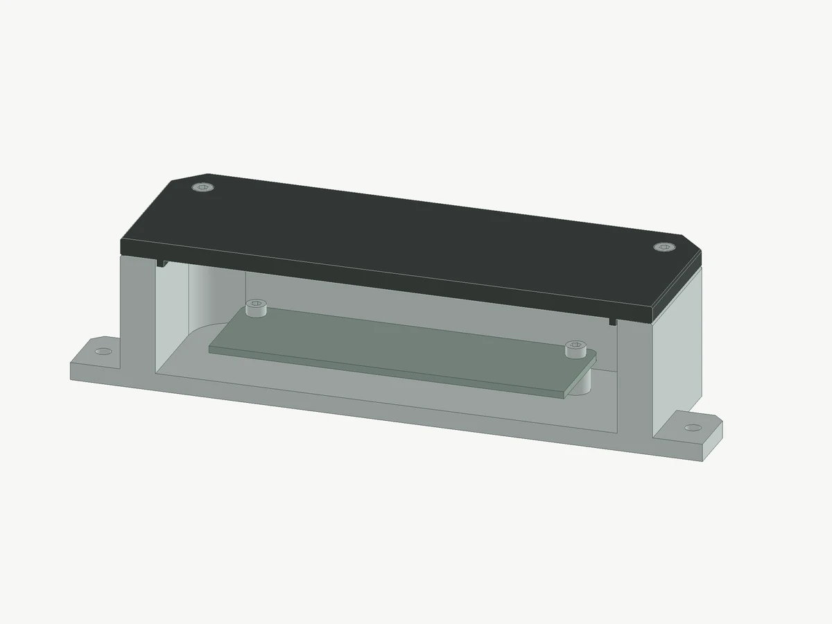
An aluminum housing with a 150 × 100 × 43 mm body, built-in mounting feet, two M16 cable entries, and a removable 100 × 60 mm internal plate. The open and section views show access to the interior and how the lid locates on the body.
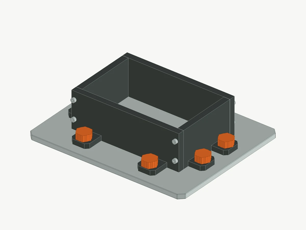
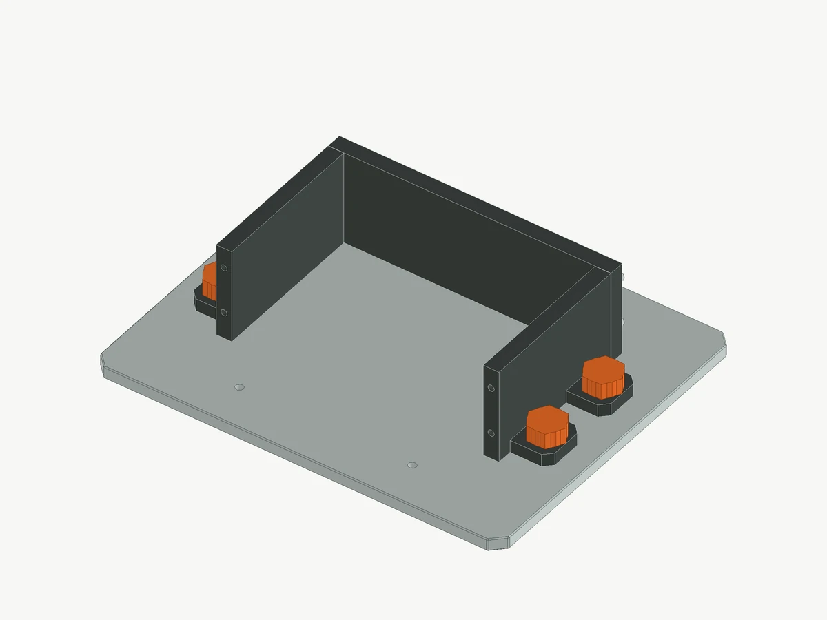
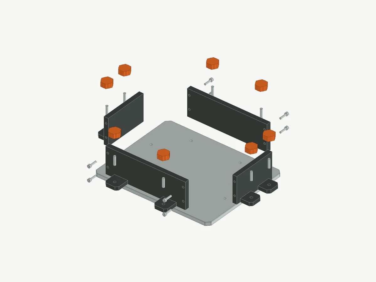
A mold box with a 160 × 100 × 60 mm cavity for containing silicone around a master pattern. Four removable walls and a separate base provide access for setup and demolding. The views show the assembly and its individual components.
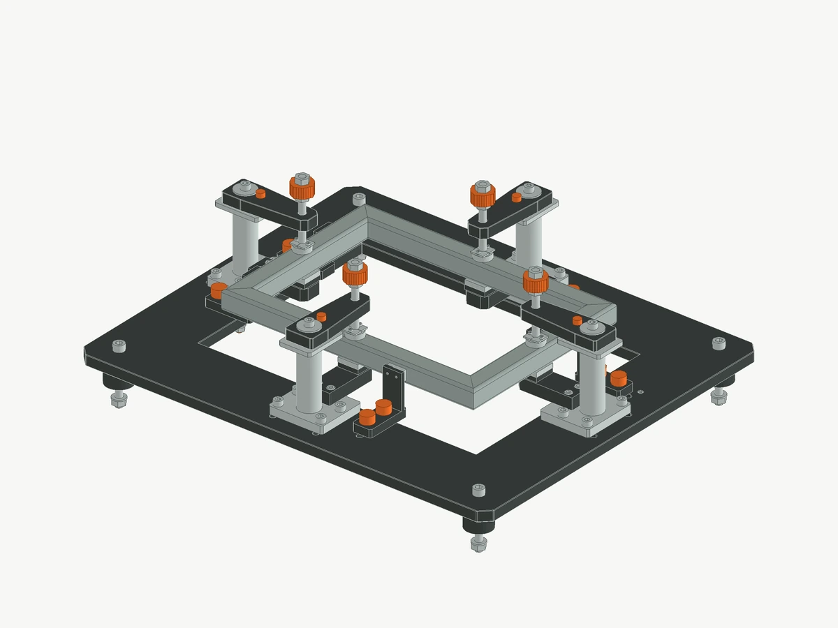
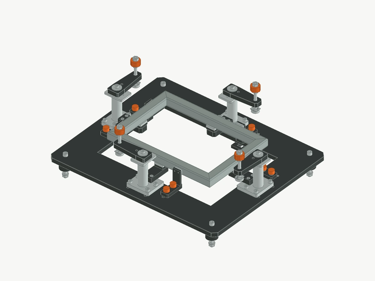
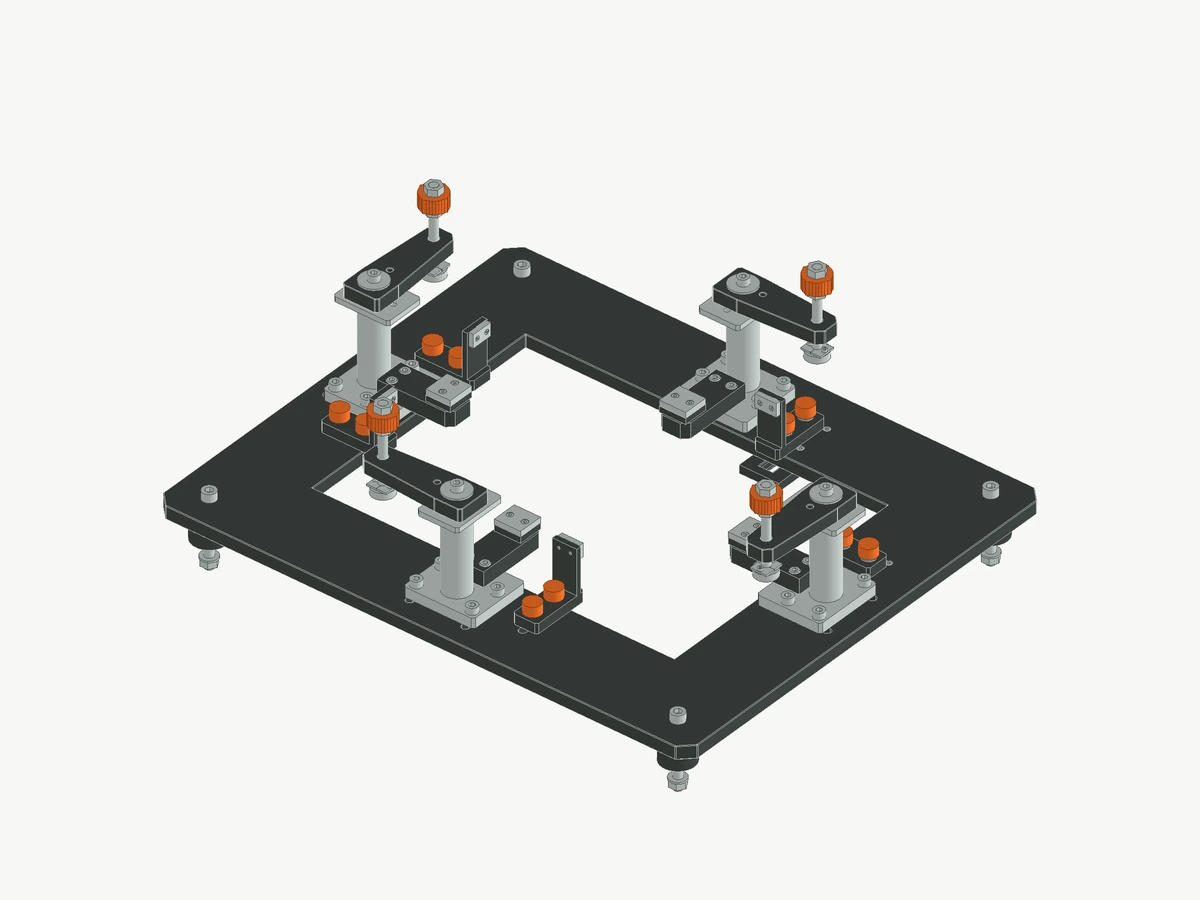
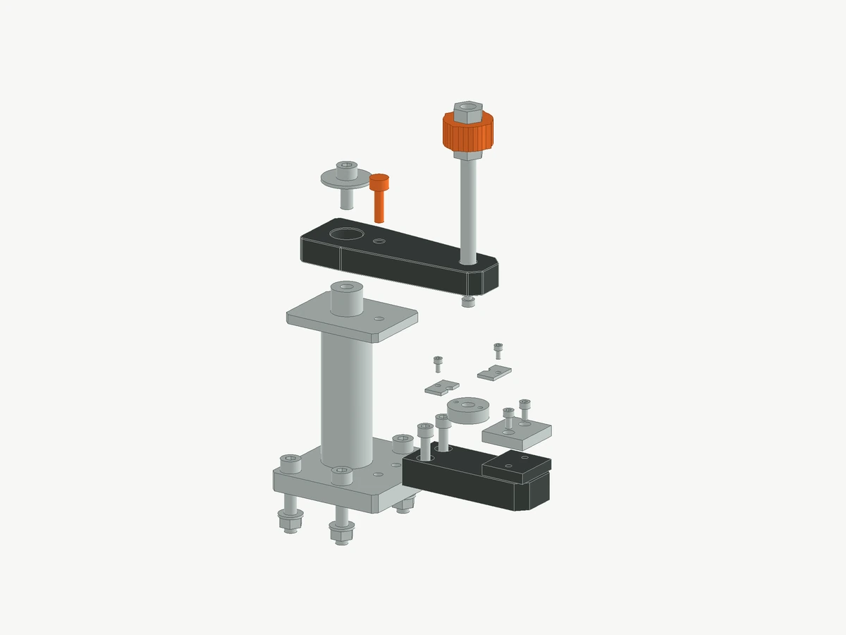
A manual fixture for positioning and tack-welding a 400 × 280 mm rectangular frame made from 30 × 30 × 2 mm tube. Four swing-away screw clamps hold the frame against replaceable supports and contact pads; withdrawable setup stops allow it to be lifted out. Finish welding is carried out separately.